The patch antenna developed for 436MHz by Greg (VK3BLG) in 2003 is a remarkable antenna for amateur satellite work. The four element antenna array has demonstrated about 16dbi gain, a remarkable figure for its compact size. The truncated cut to the radiating elements creates the Right Hand Circular (RHC) radiation pattern ideal for most amateur satellite communication.
- Patch Antenna Array Calculator
- Patch Array Antenna Gain Calculator
- Patch Antenna Array Calculator For Sale
- Patch Antenna Array Calculator Online
Intended to work as the up link antenna for AO40 my version was only used on two occasions with excellent results before the demise of AO40 in early 2004.
Among the advantages of this type of antenna we can emphasize the low cost, small size, low profile, easy to manufacture and easy to implement, among its disadvantages are narrow bandwidth or low gain. The purpose of this project is design and analysis an array of Patch antenna at 2.45 GHz with circular polarization. The help of various array configurations, feeding methods, ays are used to scan the beam of an antenna system, to increase the directivity, gain and enhance various other functions which would be difficult with single element antenna. In the microstrip array, elements can be fed by a single line. In this video, a high-gain multilayer 2x2 antenna array for the application of WLAN (wireless local area network) AP (access point) is presented. Pasternack's Microstrip Patch Antenna Calculator determines the length and width (in millimeters) of a rectangular patch antenna.
Ioperated the patch array antenna from 2003 to mid 2007 as a completely steerable array and have been able to consistently manage contacts through the UO14 and more recently AO51 satellite down to the horizon with very solid contacts down to 5 degrees above the horizon. Signal strengths of 5/9 on occasions, but typically 5/5 for most passes.
The main disadvantages of the patch array as I see it is that it has a very narrow band width, is not easily adjustable and while not a large problem for satellite work where the antenna need not be installed in a high and exposed location is its high wind loading due to the unavoidable large surface profile.

DIAGRAM OF SINGLE FEED CIRCULAR POLARISED PATCH ANTENNA (Truncated Corners) – TOP VIEW
Frequency:436.0 Mhz
Polarisation:Right Hand Circular
Patch Material:2 mm Aluminium
Patch Antenna Array Calculator
Patch Sides:316mm (Resonates at 436Mhz)

Patch Height:17mm above Ground Plane
Patch Mounting:6 mm nylon bolts using 3 nuts as spacers 75 mm diagonally from each patch corner (prior to truncation)
Ground Plane:At least 50mm larger all around the patch i.e. for a patch 316 x 316 mm, the Ground Plane should be about
416 x 416 mm
75 Ohm Point:0.115 Wavelengths from the centre ( 79.0 mm for 436.0 Mh

Truncation:40.0 mm
Element centre to centre spacing: 0.77 Wavelength or 530mm
Patch Antenna or Microstrip Antenna
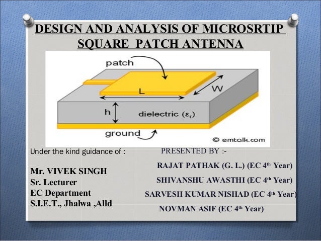
Figure 1: Cutaway view of a simple patch antenna
Patch Antenna or Microstrip Antenna
A patch antenna or microstrip antenna is a narrowband, wide-beam antenna. It is also-called printed antenna. It has two dimensional physical geometry. The simplest patch antenna uses a patch which is one-half wavelength long, so that the metal surface acts as a resonator similarly to the half-wave dipole antennas. A patch antenna is usually fabricated by mounting a shaped metal sheet on an insulating dielectric substrate, such as a printed circuit board, with a continuous metal layer bonded to the opposite side of the substrate which forms a ground plane. Hence it is easy to design and inexpensive to manufacture. Some patch antennas do not use a dielectric substrate and instead made of a metal patch mounted above a ground plane using dielectric spacers. The resulting structure is less rugged but has a wider bandwidth. Patch antennas can be designed from the UHF band to as high as 100 GHz.

Patch Array Antenna Gain Calculator
Common patch antenna shapes are square, rectangular, circular and elliptical. However the shape is not restricted. Any continuous shape is feasible. Patch antennas are mechanically rugged and can be shaped to conform to the curving skin of a vehicle. They are often mounted on the exterior of aircraft and spacecraft, or are incorporated into mobile radio communications devices. They have high polarization diversity and can be used for multiple feed points.
Figure 2: The patch antenna array of a maritime FMCW navigation radar in X-band

Advantages
- High accuracy in manufacturing, the design is executed by Photo etching.
- Easy to integrate with other devices.
- Small sized applicable for handheld portable devices.
- We can obtain high directivity using microstrip arrays.
- An array of microstrip antennas can be used to form a pattern that is difficult to synthesize using a single element.
- Smart antennas when combined with phase shifters or PIN-diode switches.
Figure 2: The patch antenna array of a maritime FMCW navigation radar in X-band
Patch Antenna Array Calculator For Sale
Figure 2: The patch antenna array of a maritime FMCW navigation radar in X-Band
Disadvantages
- Narrow band width (1%), while mobiles need (8%).
- Low efficiency, especially for short circuited microstrip antenna.
- Some feeding techniques like aperture and proximity coupling are difficult to fabricate.
- An array suffers presence of feed network decreasing efficiency.
Microstrip antennas occurred during the 1980s. Initially it was a military development, at the cost did not matter. In the 1990s this technology has also been adopted for devices for communication as a low-cost technology. But the performance of a microstrip array was well below that of a reflector antenna.
Microstrip Antennas
- are preferred for low directivity applications;
- have lower efficiency;
- suffers low efficiency caused by feed network for arrays;
- are suitable for smart antennas; if combined with phase shifters then they can provide electronic scanning;
- allow more accurate manufacturing by photo etching;
- feeding is by coupling or coax feed lines.
Patch Antenna Array Calculator Online
Reflector Antennas
- are performed for high directivity applications;
- have higher efficiency;
- suffers blockage caused by fixation Struts;
- uses mechanical scanning;
- have less accuracy, sometimes parabolic surfaces are rough;
- use other antenna (dipole, monopole, apertures, etc) as a feed.